Test Index
CBSE Class 12 Physics 2016 Delhi Set 1 Paper
© examsnet.com
Question : 24 of 26
Marks:
+1,
-0
SECTION - E
(i) An a.c. source of voltage is connected to a series combination of and . Use the phasor diagram to obtain expressions for impedance of the circuit and phase angle between voltage and current. Find the condition when current will be in phase with the voltage. What is the circuit is this condition called? (ii) In a series circuit and power factor of the circuit is . When capacitor with capacitance such that put in series, the power factor becomes Calculate . OR (i) Write the function of a transformer. State its principle of working with the help of a diagram. Mention various energy losses in this device. (ii) The primary coil of an ideal step up transformer has 100 turns and transformation ratio is also 100 . The input voltage and power are respectively and . Calculate : (a) number of turns in secondary (b) current in primary (c) voltage across secondary (d) current in secondary (e) power in secondary
Solution:
(i) Obtaining expression for impedance & phase angle Condition of current being in phase with voltage Naming of circuit condition (ii) Calculation of (i) 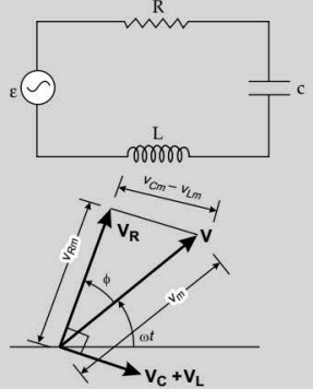 From Figure where From Figure Condition for current and voltage are in phase: Circuit is called Resonant circuit. (ii) Power factor Power factor when capacitor of reactance is put in series in the circuit ∴ OR (i) Function of transformerWorking principle and diagramVarious energy losses (two) (ii) Calculation of part (a), (b), (c), (d) & (e) (i) Conversion of ac of low voltage into ac of high voltage & vice versa. Mutual induction : When alternating voltage is applied to primary windings, emf is induced in the secondary windings.
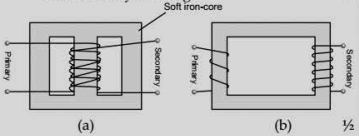 Energy losses:(a) Leakage of magnetic flux(b) Eddy currents(c) Hysteresis loss(d) Copper loss (ii) Transformation ratio (a) Number of turns in secondary coil (b) Input Power Input voltage current in primary (c) (d) (e) Power in secondary = Power in Primary
© examsnet.com
Go to Question: