Test Index
CBSE Class 12 Physics 2019 Outside Delhi Set 1 Paper
© examsnet.com
Question : 27 of 27
Marks:
+1,
-0
(a) Describe briefly, with the help of a circuit diagram, the method of measuring the internal resistance of a cell. (b) Give reason why a potentiometer is preferred over a voltmeter for the measurement of emf of a cell. (c) In the potentiometer circuit given below, calculate the balancing length . Give reason, whether the circuit will work, if the driver cell of emf is replaced with a cell of , keeping all other factors constant. 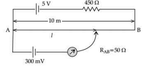 OR (a) State the working principle of a meter bridge used to measure an unknown resistance. (b) Give reason (i) Why the connections between the resistors in a metre bridge are made of thick copper strips, (ii) Why is it generally preferred to obtain the balance length near the mid-point of the bridge wire. (c) Calculate the potential difference across the resistor in the given electrical circuit, using Kirchhoff's rules.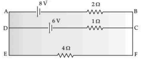
Solution:
Circuit diagram and describing the method to measure internal resistance of cell by potentiometer Reason Calculating balancing length and reason (circuit works or not) (a) Circuit diagram : 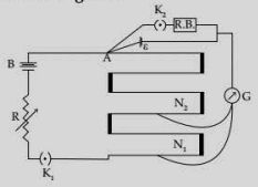 Brief description: Plug in the key and keep unplugged and the find the balancing length such that : .....1 With the key also plugged in find out balancing length again such that : .....(2) (b) The potentiometer is preferred over the voltmeter for measurement of e.m.f. of a cell because potentiometer draws no current from the voltage source being measured. (c) With driver cell current in the circuit is Potential difference across . Hence the circuit will not work. OR (a) The circuit diagram of the metre bridge is as shown below:
 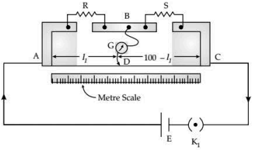 Working Principle: The working principle of the meter bridge is the same as that of a Wheatstone bridge. The Wheatstone bridge gets balanced when: For the metre bridge, circuit shown above, this relation takes the form
 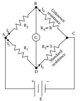 Determination of unknown Resistance : In the circuit diagram shown above, is taken as a known standard resistance. We find the value of the balancing length , corresponding to a given value of . We then use the relation: to calculate . By choosing (at least three) different values of , we calculate each time. The average of these values of gives the value of the unknown resistance. (b) (i) This is to ensure that the connections do not contribute any extra, unknown, resistances in the circuit. (ii) This is done to minimize the percentage error in the value of the unknown resistance. Alternatively, This is done to have a better "balancing out" of the effects of any irregularity or non-uniformity in the metre bridge wire. (c) This can help in increasing the sensitivity of the metre bridge circuit.
 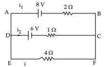 Apply the current junction rule of Kirchhoff's Law at point .....(i) Apply Kirchhoff's Voltage rule for the mesh AEFBA or, .....(ii) Apply Kirchhoff's voltage rule for mesh DEFCD .......(iii) Adding equation (ii) and (iii), we get Now, the potential difference across resistor
© examsnet.com
Go to Question: