Concept:In a common emitter (CE) amplifier, the output signal is inverted with respect to the input signal, producing a phase shift of
180∘.
Explanation:The common emitter configuration is the most widely used BJT amplifier circuit.
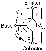
Here, the input is applied between the base and emitter, while the output is taken between the collector and emitter.
When the input voltage increases, the base current
IB increases, which in turn increases the collector current
IC.
A larger
IC causes a greater voltage drop across the collector resistor
RC.
As a result, the output voltage
VCE decreases.
Thus, a rise in the input produces a fall in the output, meaning the output is inverted.
This inversion corresponds to a phase shift of
180∘ between input and output.
In contrast, the common base and common collector configurations give a
0∘ phase shift.
The table below compares the key characteristics of the three BJT configurations.
Answer:The common emitter configuration shifts the input-output phase by
180∘.
Therefore, the correct option is C. 180 degree.