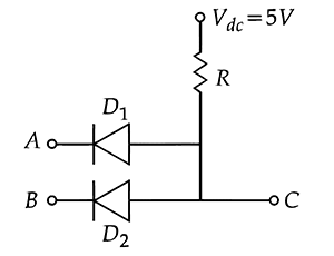
Concept:The circuit uses two diodes with their cathodes connected to inputs A and B, and a pull-up resistor R to V
dc. It functions as an AND gate where the output C is HIGH (5 V) only when both inputs are HIGH (5 V), otherwise it is LOW (0 V).
Explanation:We assume positive logic: LOW = 0 V (logic 0), HIGH = 5 V (logic 1).
Supply voltage
Vdc=5 V is connected to output C through resistor R.
Diodes
D1 and
D2 are connected with their cathodes (n-side) to inputs A and B respectively. They act as switches that conduct when forward-biased (cathode lower than anode).
Case 1:
A=0,
B=0 (both LOW).
Both diodes are forward-biased (anode at
+5 V, cathode at
0 V). They conduct, pulling output C to approximately 0 V. Output C = 0.
Case 2:
A=0,
B=1 (one LOW, one HIGH).
Diode
D1 (cathode at 0 V) is forward-biased, conducting current to ground. This forces output C to near 0 V. Diode
D2 (cathode at 5 V) is reverse-biased (off). Output C = 0.
Case 3:
A=1,
B=0 (one HIGH, one LOW).
Diode
D2 is forward-biased, conducting to ground at B, so output C stays at 0 V. Diode
D1 is reverse-biased. Output C = 0.
Case 4:
A=1,
B=1 (both HIGH).
Both cathodes are at 5 V, same as anodes. Diodes are reverse-biased (no current). No voltage drop across R, so output C is at supply voltage 5 V. Output C = 1.
Truth table:
The output is HIGH only when both inputs are HIGH. This is the characteristic of an AND gate.
Answer:The circuit functions as an AND gate. Therefore, the correct option is A.